SYSTEM DOWNLOADS

CONTROLLER FIRMWARE

Latest Version: V1.2.7
Release Date: 2025-04-28

FIRMWARE UPDATE TOOL

Tool Version: V1.0.3
Compatible: Windows 10/11

new upgrade

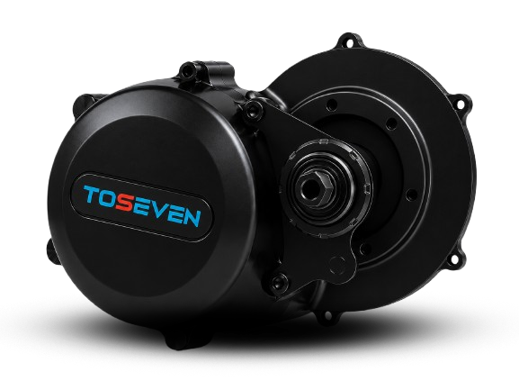
DM01 - 750w
conversion kit

750W | HEAVY DUTY · POWER & ENDURANCE

For extreme terrain and heavy cargo.

750W

Extreme Power

160 N.M

Torque

5.8 Kg

Weight

DM01- 750w

MOTOR SPECIFICATIONS

Rated Power

750W

Rated Voltage

48V/52V

Reduction Gear Ratio

40.27:1

Max.Speed

160rpm

Max Torque

160N.m

Sensor Style

Cadence/ Torque sensor

Chainring Compatibility

Standard 46T (Optional 38T–52T)

BB Axle

~68mm~73mm
~100mm~110mm
~110mm~120mm

Noise Level

<50dB

Work Temperature

-20℃ ~ 50℃

Motor Weight

5.8Kg

Waterproof Level

IP65

DM01-750W ADVANCED CAPABILITIES

Extreme Torque on Steep Climbs

Up to 160N.m on Strong Grade Climbing - Conquer Every Peak

Cargo Power & Efficiency

Built to handle heavy loads with ease and efficiency

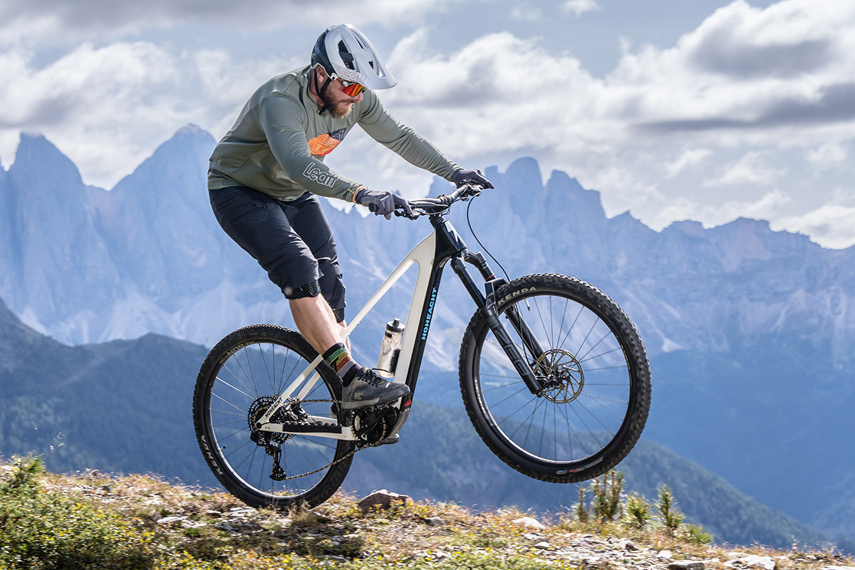
All-Weather Performance

IP65 Certified to perform in all weather conditions
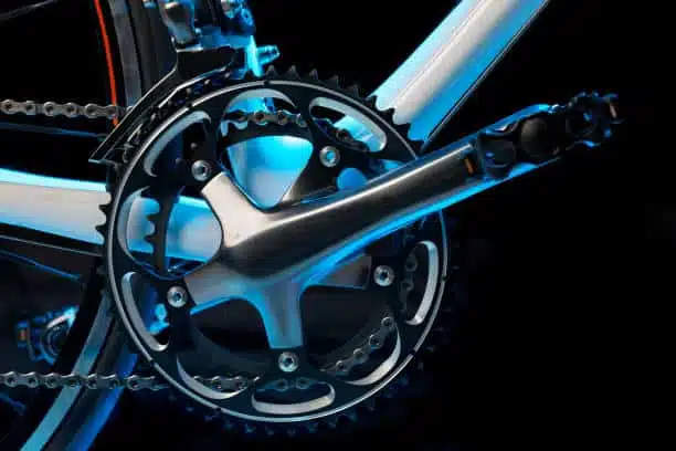
Intelligent Power Control

Torque & Cadence sensors deliver smooth and natural pedal assistance
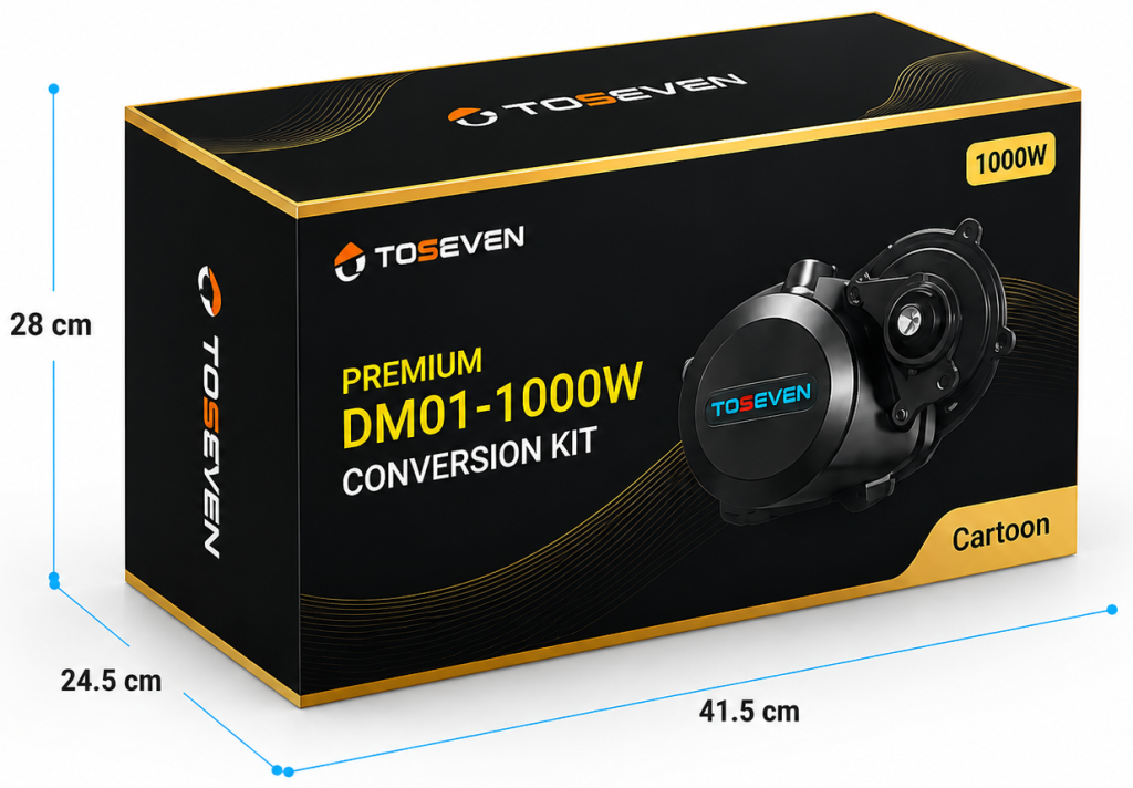
PREMIUM

DM01- 750w
conversion kit

Torque + Cadence Sensing

Natural, responsive pedal assistance.

All-Terrain Ready

Built to handle city streets to rugged trails.

Plug & Play Wiring

Complete electrical system for easy installation.

Easy to Install

Plug & Play System

Lightweight Design

Compact & Portable

High Efficiency

Longer Range

Reliable & Safe

Multiple Protection

Conversion kit contents

DM01 750W Mid-Drive Motor + 13 Components

01.

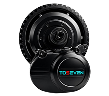
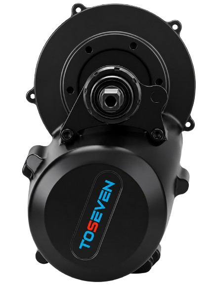
DM01 Mid Motor

02.

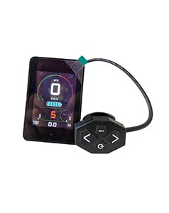
T24 Display

03.

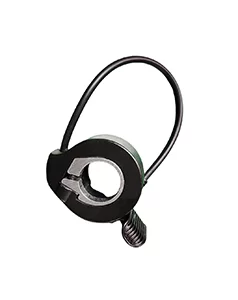
Throttle

04.

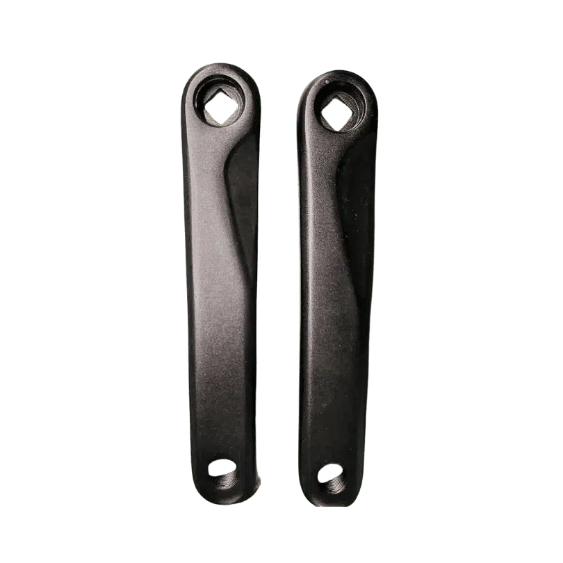
Cranks

05.

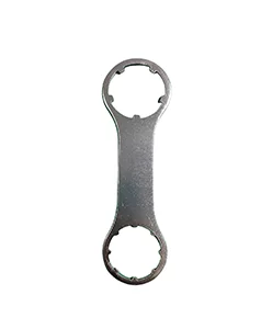
Installation Tool

06.

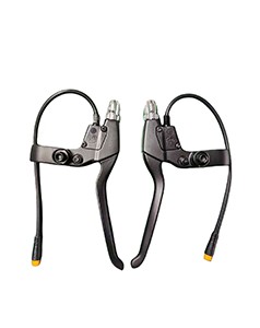
Brake Lever

07.

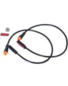
Speed Sensor

08.

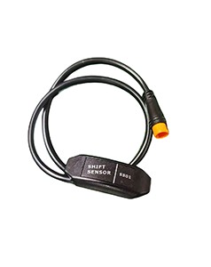
Shift Sensor

09.

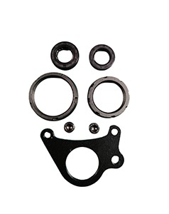
Locking Rings

10.

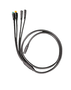
1T4 E-Bus Wires

11.

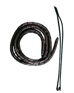
Cable Wraps

12.

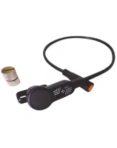
Brake Sensor

13.

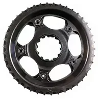
46T Chainring

Installation &
Compatibility

Select your frame standard to view the exact components included in your kit.

BB = 68-73mm

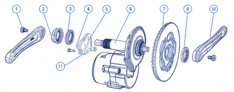
EXPLODED DIAGRAM

STANDARD FRAME COMPATIBILITY (68–73MM)

BB Width

Standard Chainline (CL)

Optional Chainline (CL)

BB Width

68 mm

Standard Chainline (CL)

50 mm

Optional Chainline (CL)

59 mm

BB Width

73 mm

Standard Chainline (CL)

52.5 mm

Optional Chainline (CL)

61.5 mm

included compontents

#

Component Part

Specification

Qty

1

Component Part

Axle Screw

Specification

M8 × 1 × 15

Qty

2

2

Component Part

Left Crank

Specification

170mm

Qty

1

3

Component Part

Decoration Cap

Specification

Not Specified

Qty

1

4

Component Part

Non-standard Nut

M33.5X1.5

Specification

Qty

1

5

Component Part

Screw (Hardware Variance)

Specification

M6x16mm (for 68mm BB) M6x20mm (for 73mm BB)

Qty

2

6

Component Part

Reinforced Plates

Specification

Not Specified

Qty

1

7

Component Part

Locknut

Specification

M42X1.5

Qty

1

8

Component Part

Right Crank

Specification

170mm

Qty

1

9

Component Part

Bushing (Hardware Variance)

Specification

Not required (for 68mm BB) Φ6X5 (for 73mm BB)

Qty

2

BB = 100-110mm، 110-120mm

EXPLODED DIAGRAM

STANDARD FRAME COMPATIBILITY (100-110MM, 110-120MM)

BB Width

Standard Chainline (CL)

Optional Chainline (CL)

BB Width

100 mm

Standard Chainline (CL)

66 mm

Optional Chainline (CL)

75 mm

BB Width

110 mm

Standard Chainline (CL)

71 mm

Optional Chainline (CL)

80 mm

BB Width

120 mm

Standard Chainline (CL)

76 mm

Optional Chainline (CL)

85 mm

included compontents

#

Component Part

Specification

Qty

1

Component Part

Axle Screw

Specification

M8 × 1 × 15

Qty

2

2

Component Part

Left Crank

Specification

170mm

Qty

1

3

Component Part

Decoration Cap

Specification

Standard Cap (Not required for 120mm BB)

Qty

1

4

Component Part

Non-standard Nut

M33.5X1.5

Specification

Qty

1

5

Component Part

Screw (Hardware Variance)

Specification

M6X50 (for 100mm BB)
M6X60 (for 110mm BB)
M6X70 (for 120mm BB)

Qty

2

6

Component Part

Reinforced Plates

Specification

Not Specified

Qty

1

7

Component Part

Locknut

Specification

M42X1.5

Qty

1

8

Component Part

Right Crank

Specification

170mm

Qty

1

8

Component Part

Crankset

Specification

46T

Qty

1

9

Component Part

Lock Washer (Hardware Variance)

Specification

Φ6X32 (for 100mm BB)
Φ6X42 (for 110mm BB)
Φ6X52 (for 120mm BB)

Qty

2

INSTALLATION CENTER

Install with Confidence

Follow the video and step-by-step guide to install your DM01 mid drive motor.

Estimated Time

25-35 Minutes

Difficulty

Easy

STEP 1 OF 9

Tools & Preparation

Prepare your bicycle, workspace, and tools before starting the installation.

Preparation Checklist

TOOLS REQUIRED

1

Special Wrench

Included in the kit

2

6mm Allen Wrench

General tool

3

8mm Allen Wrench

General tool

Before Continuing

BEFORE YOU BEGIN

Compatibility Notice

Use only genuine TOSEVEN accessories and components supplied with the kit.

Safety Reminder

Read the Installation Precautions PDF before beginning installation.

Installation Precautions PDF

Important safety and installation information

STEP 2 OF 9

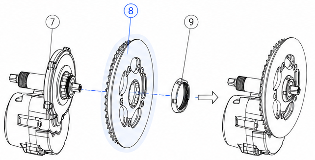
Chain-ring Installation

Install the chain-ring onto the motor output shaft and secure it using the supplied lock ring.

FOLLOW THESE STEPS

1- Position

Place the chain-ring onto the motor.

2- Align

Rotate until the splines line up.

3- Secure

Install the lock ring.

4- Tighten

Use the special wrench.
Torque: 15 Nm.

TORQUE SPECIFICATION

15 Nm

EXPLODED VIEW

If the chain-ring doesn't slide on easily, rotate it slightly until it aligns. Do not force it.

COMPONENTS USED

REQUIRED TOOL

Special Wrench

Included in the kit

FINAL CHECK

STEP 3 OF 9

Motor Mounting

Insert the assembled motor into the bicycle’s bottom bracket and rotate it into its correct position.

FOLLOW THESE STEPS

1- Position

Lift the motor beneath the bottom bracket.

2- Insert

Guide the spindle through the bottom bracket shell.

3- Rotate

Rotate the motor upward until it sits flush against the frame.

4- Support

Hold the motor in place while preparing the reinforcement plate.

TIP

The motor is not secured until the reinforcement plate is installed in the next step.

REFERENCE IMAGE

Motor inserted and correctly positioned inside the frame.

BEFORE CONTINUING

HELPFUL TIP

Support the motor during installation. It will remain loose until the reinforcement plate is installed in the next step.

STEP 4 OF 9

Reinforcement Plate Installation

Install the reinforcement plate using the correct hardware for your selected bottom bracket width.

FOLLOW THESE STEPS

1- Position

Place the reinforcement plate against the motor mounting face.

2- Select Hardware

Use the correct spacer or bushing for your BB configuration.

3- Install Screws

Insert both supplied M6 screws.

4- Tighten

Alternately tighten each screw until the plate sits flush.

TIP

Tighten both screws evenly. Do not fully tighten one side before the other.

BOTTOM BRACKET CONFIGURATION

Use the hardware shown for the selected BB width only.

BEFORE CONTINUING

HELPFUL TIP

If the plate does not sit flat, stop and verify that the correct BB width configuration is selected.

STEP 5 OF 9

Install Non-standard Nut

Secure the motor by installing and tightening the non-standard locknut supplied with the kit.

Installation Steps

1- Position the locknut

Align the non-standard locknut with the motor axle threads.

2- Hand-tighten first

Thread the locknut by hand until it seats against the reinforcement plate.

3- Tighten using the special wrench

Use the supplied installation wrench to fully tighten the locknut

4- Verify installation

Confirm the motor is firmly secured with no movement before continuing.

Installation Check

✓ Locknut fully seated
✓ Motor cannot rotate
✓ Reinforcement plate remains flush

BOTTOM BRACKET CONFIGURATION

Locknut Notes

(4) Part #4

Non-standard Locknut

Important

Tip

Hold the motor in its final position while tightening the locknut to prevent it from rotating.

STEP 6 OF 9

Decoration Cap Installation

Install the decoration cap onto the motor to complete the motor assembly before installing the crank arms.

Installation Steps

1- Align the decoration cap

Align the decoration cap with the motor opening.

2- Thread clockwise

Turn the decoration cap clockwise by hand.

3- Hand tighten

Tighten by hand until the cap is fully seated and flush.

Installation Check

Tip

Ensure the decoration cap is fully seated to protect the motor opening from dust and water.

STEP 7 OF 9

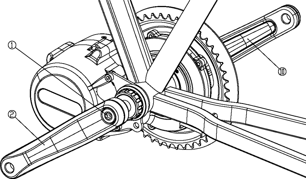
Crank Installation

Install the left and right crank arms onto the motor spindle, then securely tighten both axle bolts before riding.

FOLLOW THESE STEPS

1-Install the Right Crank

Slide the right crank arm fully onto the motor spindle.

2-Install the Left Crank

Slide the left crank arm onto the opposite side of the spindle until fully seated.

3-Install the Axle Bolts

Insert the axle bolt into each crank arm and thread it in by hand until seated.

4- Tighten Both Axle Bolts

Using an 8 mm Allen wrench, tighten both axle bolts to 35–40 Nm.

Tightening Reminder

Tighten both axle bolts to 35–40 Nm.
Using a torque wrench is recommended to achieve the correct tightening force and ensure a secure crank installation

CRANK INSTALLATION

Both crank arms should be fully seated on the spindle before tightening the axle bolts.

REQUIRED TOOL

8 mm Allen Wrench

General Tool

INSTALLATION CHECK

HELPFUL TIP

Thread each axle bolt by hand before tightening with the Allen wrench. This helps prevent cross-threading and ensures both crank arms seat correctly on the spindle.

STEP 8 OF 9

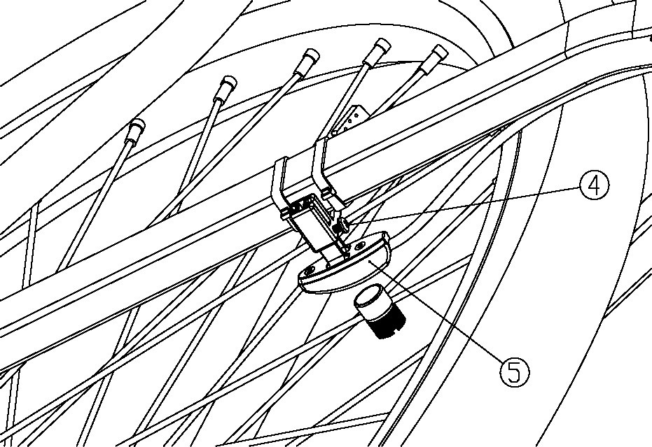
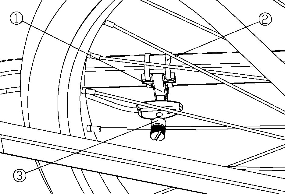
Speed Sensor Installation

Install the speed sensor and spoke magnet, then adjust the gap so the sensor can accurately detect wheel speed.

FOLLOW THESE STEPS

1-Mount the Sensor

Secure the speed sensor to the chainstay using the two supplied cable ties.

2-Install the Magnet

Attach the spoke magnet directly opposite the sensor.

3-Align the Sensor

Move the sensor until the magnet passes directly in front of the circular mark.

4- Secure the Position

Tighten the adjustment screw once the gap is correct.

REFERENCE IMAGES

1-Mount the Sensor

2-Install & Align the Magnet

Recommended gap: 2–10 mm between the sensor and magnet.

BEFORE CONTINUING

HELPFUL TIP

Rotate the wheel by hand after installation. The magnet should pass directly in front of the sensor without touching it. If contact occurs, loosen the sensor, adjust its position, and retighten the screw.

STEP 9 OF 9

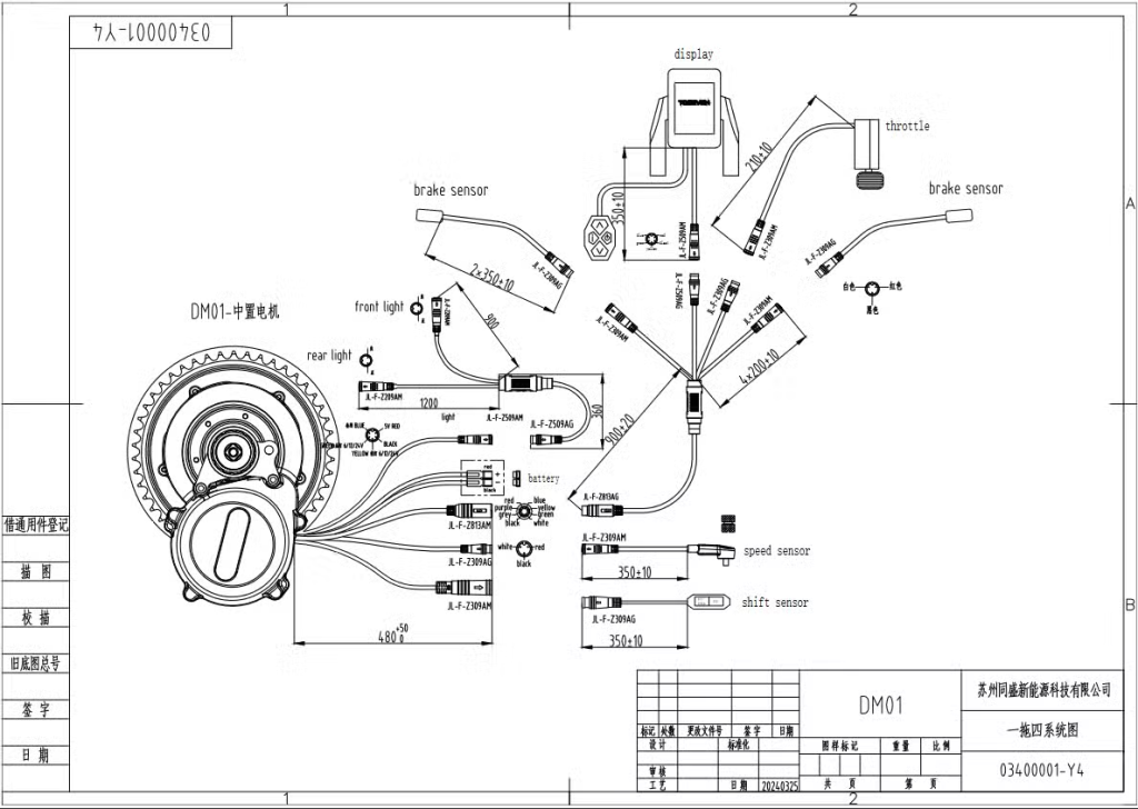
Wiring & Setup

Connect all electrical components to the motor harness and secure the wiring before powering on the system.

FOLLOW THESE STEPS

1- Connect the display

Connect the display cable to the matching connector on the motor harness.

2-Connect accessories

Connect the throttle, brake sensors, lights, gear sensor, and any other optional accessories you are using.

3-Connect the speed sensor

Plug the speed sensor connector into the matching motor harness connector.

4- Secure the wiring

Route the wiring along the bicycle frame and secure it with zip ties. Keep cables away from moving parts and sharp edges.

TIP

Leave enough cable slack near the handlebars so they can turn fully left and right without pulling on the wiring.

WIRING DIAGRAM

Connect each component only to its matching waterproof connector. Never force a connector if it does not align.

BEFORE POWERING ON

HELPFUL TIP

Perform a final inspection before switching the system on. Proper cable routing helps prevent damage and ensures reliable operation.