Extreme Power
Torque
Weight

Up to 120N.m Peak Torque for Confident Climbing Performance

500W Output Designed for Commuting, Touring, and Everyday Adventures

IP65 Protection Ensures Dependable Performance in Various Conditions
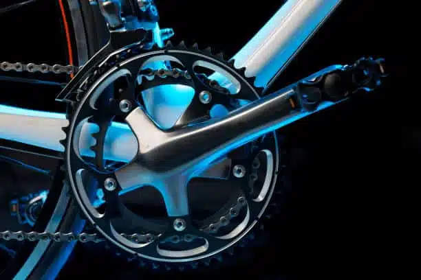
Torque & Cadence Sensors Deliver Smooth and Natural Pedal Assistance

Natural, responsive pedal assistance.
Built to handle city streets to rugged trails.
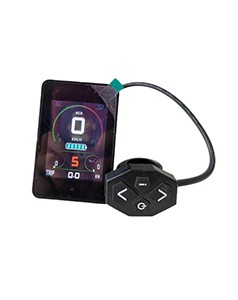
Complete electrical system for easy installation.
Plug & Play System
Compact & Portable
Longer Range
Multiple Protection


Select your frame standard to view the exact components included in your kit.


Install with Confidence
Follow the video and step-by-step guide to install your DM01 mid drive motor.
25-35 Minutes
Easy
Prepare your bicycle, workspace, and tools before starting the installation.
Preparation Checklist
TOOLS REQUIRED

Included in the kit

General tool

General tool
Before Continuing
BEFORE YOU BEGIN
Use only genuine TOSEVEN accessories and components supplied with the kit.
Read the Installation Precautions PDF before beginning installation.
Important safety and installation information
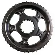
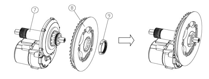
Install the chainring onto the DM02 drive unit output shaft and secure it using the supplied chainring locknut.
Align the chainring splines with the drive unit output shaft.
Components: ⑦ Drive Unit ⑧ Chainring
Carefully slide the chainring onto the shaft until it is fully seated.
Thread the M42 chainring locknut onto the shaft.
Component: ⑨ Chainring Locknut
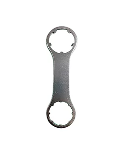
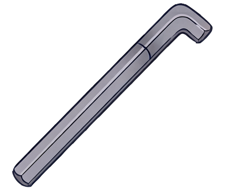
Use the Toseven installation wrench to tighten the locknut.
15–20 N·m
Maximum torque: 20 N·m
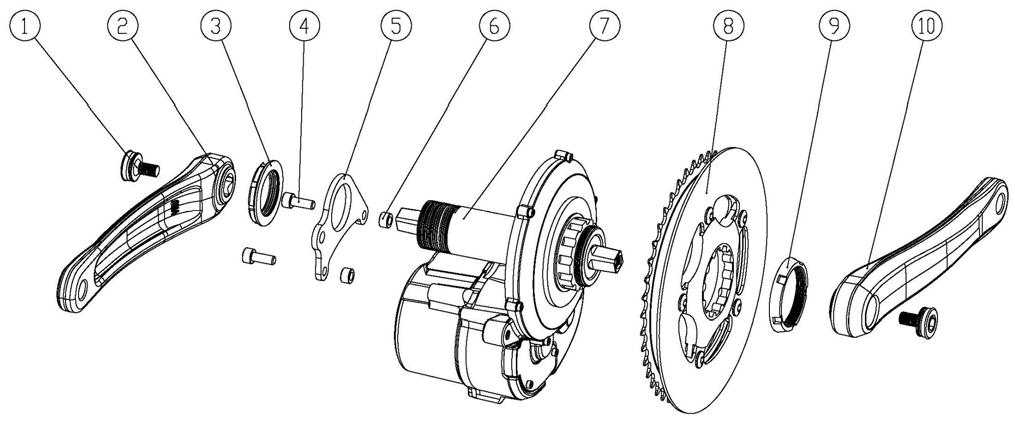
EXPLODED VIEW
The chainring locknut uses a left-hand thread.
DO NOT exceed 20 N·m.
COMPONENTS USED
REQUIRED TOOL

Included in the kit
FINAL CHECK
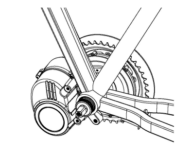
Install the DM02 drive unit into the bicycle frame and ensure it is correctly seated inside the bottom bracket shell.
Insert the drive unit from the drive side (right side) of the frame.
Align the drive unit with the bottom bracket shell and ensure the motor position is correct.
Carefully push the drive unit until it is fully seated against the BB shell.
Do not use a hammer or excessive force during installation.
If resistance occurs:
Remove the drive unit
Check the BB shell for burrs or weld irregularities
Reinstall after correcting the issue
DRIVE UNIT POSITIONING
Insert the drive unit from the drive side (right side) of the frame and push it in until it is fully seated against the bottom bracket shell.
Ensure the motor is straight and aligned with the BB shell before pushing in.
COMPONENT USED
INSTALLATION CHECK
The motor will be secured in the next step with the anti-rotation bracket and mounting hardware.
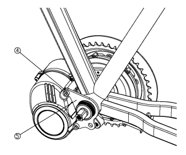
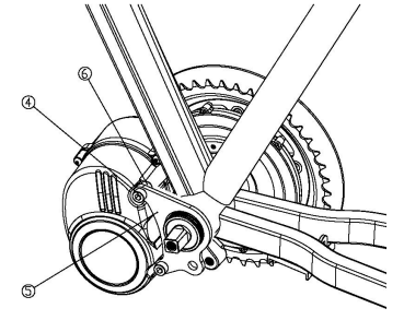
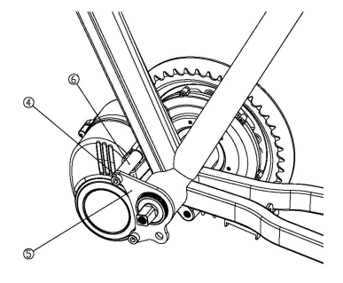
Secure the DM02 drive unit using the anti-rotation bracket and the correct mounting hardware for your bottom bracket width.
Place the anti-rotation bracket flat against the frame's bottom bracket face.
Choose your bottom bracket width in the center panel to view the correct mounting hardware.
Install the correct M6 mounting bolts and spacer sleeves according to your selected configuration.
Tighten both mounting bolts evenly.
9–10 N·m
Tighten both bolts evenly.
BOTTOM BRACKET CONFIGURATION
Installation Guide
Use Diagram A
No spacer between bracket & motor.
Measure your bottom bracket width accurately before proceeding to ensure the correct hardware configuration.
COMPONENT USED
REQUIRED TOOL

(Included in the kit)
FINAL CHECK
Secure the DM02 drive unit by tightening the main lockring.
Rotate the drive unit clockwise until the motor housing sits firmly against the frame.
Thread the M33.5 Main Lockring onto the BB spindle by hand.
Use the Toseven Installation Wrench to tighten the lockring.
45–50 N·m
Use the Toseven Installation Wrench.
Ensure the motor housing is fully seated against the frame before tightening the main lockring. Improper positioning may result in motor movement, loosening, or abnormal noise during riding.
BOTTOM BRACKET CONFIGURATION
Make sure the motor housing remains pressed firmly against the frame throughout tightening.
COMPONENT USED
REQUIRED TOOL

(Included in the kit)
FINAL CHECK
Ensure your frame is compatible with mid-drive systems. Carbon frames require manufacturer approval. For lightweight aluminum frames, use the lower end of the torque range (45 N·m).
Learn more in the Compatibility Guide ➔
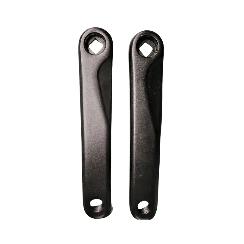
Install the left and right crank arms onto the square taper spindle and secure them with the supplied fixing bolts.
Align both crank arms at 180°.
Fully seat both crank arms onto the square taper spindle.
Thread the crank arm fixing bolts ① into the spindle.
Tighten the fixing bolts to 35–40 N·m.
- Light grease on bolt threads only
- Do not lubricate taper interface
- Use calibrated torque wrench only
35–40 N·m torque.
REQUIRED TOOL
General Tool
INCLUDED HARDWARE
FINAL CHECK
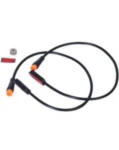
Install the speed sensor and magnet on the rear wheel. Ensure proper alignment and clearance for accurate speed signal.
Incorrect alignment or clearance may result in speed signal loss or intermittent motor assistance.
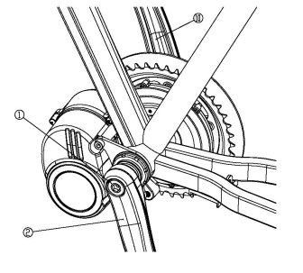
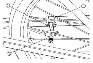
1. Attach the speed sensor ① to the chainstay using cable ties ②.
2. Loosen adjustment screw ④.
3. Adjust the sensor position to achieve correct clearance (2–5 mm).
4. Tighten adjustment screw ④ and secure cable ties ②.
If speed signal error or drive unit assist failure occurs, re-check alignment immediately.
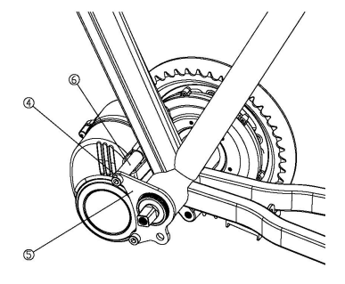
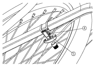
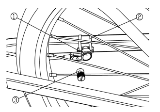
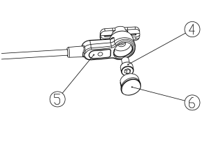
1. Align the speed sensor ① with the frame mounting point.
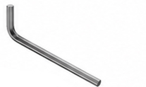
2. Secure the sensor using the M5×8 screw ④ with a 3mm Allen wrench.
3. Install the decorative cap ⑥ after securing the sensor.
4. Ensure the magnet passes the receiver with correct clearance (5–15 mm).
If speed signal error or drive unit assist failure occurs, re-check magnet position, sensor alignment, and clearance distance immediately.
REQUIRED TOOL

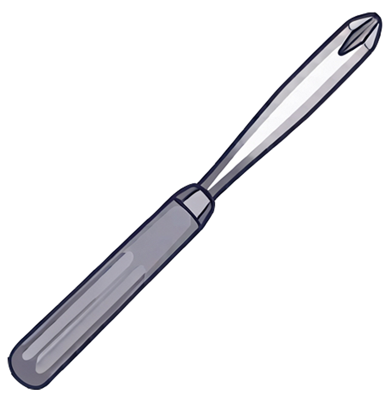
Medium Phillips Screwdriver

3mm Allen Wrench
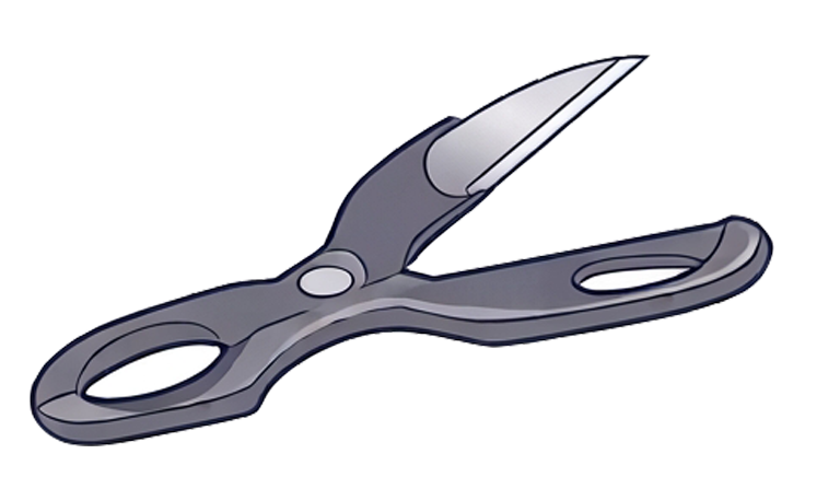
Scissors / Side Cutters
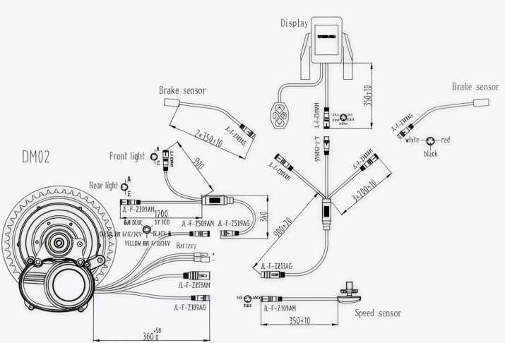
COMPONENT LEGEND (BOTH MODELS)
FINAL CHECK
Connect the DM02 system and route the cables safely.
Connect the EB-Bus connectors to the correctly labeled drive-unit ports.
Keep cables away from moving parts, compression points, sharp bends, and tight gaps around the motor.
Align the waterproof connector arrows and push each connector fully together until the sealing ring is seated.
Do not apply excessive force during connection or disconnection. All connectors are mechanically keyed to prevent incorrect installation.
SYSTEM WIRING DIAGRAM
(optional / system dependent)
(user-provided)
(system dependent)
(Toseven proprietary system)
CABLE ROUTING
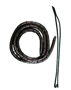
Route all cables away from:
Align the waterproof connector arrows before insertion. Push until the sealing ring is fully seated to ensure proper sealing and electrical contact.
Keep pedals completely unloaded during power-on.
- Do not rest feet on the pedals during startup.
- Ensure pedals are completely unloaded before powering on.
Improper calibration may cause abnormal assist, delayed or excessive power output.
Before your first ride, verify that all critical fasteners are correctly tightened and the system is secure.
Before first ride, verify the following:
Re-check all fasteners after the first 50 km of riding.
Direct-from-factory electric drive systems for OEM manufacturers.
Suzhou Toseven New Energy Technology Co., Ltd. — a professional electric bicycle motor manufacturer integrating R&D, production, sales and after-sales departments.
© 2026 TOSEVEN. All specifications subject to revision.